вторник, 1 января 2019 г.

Ingenic Halley2, Uboot, Test push button and LED

I add to my stand 2 components:
1) a push button;
2) a LED.

Connection is follow.
A push button to pin BOOT_SEL0_PB28.
A LED to pin I2C0_SDA_SCC_DATA_PB24.
For more information about pins see X1000 Datasheet.

Both pins are in a group of port B. Their internal numbers are 60 and 56 respectively.

I made several scripts to test their functionality. They are here.

Update 07.01.2019. This is the photo of my stand.

Also I made the demo video with working script.


среда, 19 декабря 2018 г.

Ingenic Halley2, Uboot, loadb command

Be default Uboot version has not loadX commands. I wanted to test loading programs by serial line. So I did changes in board configuration to add set of commands loadX.
I added to configuration file (include/configs/halley2.h) follow lines:
#define CONFIG_CMDLINE_EDITING
#define CONFIG_CMD_LOAD
#define CONFIG_USE_XYZMODEM
#define CONFIG_CMD_LOADB
#define CONFIG_CMD_LOADS

After that new command appeared in Uboot command line interface.

When Uboot is compiled simple standalone program is compiled too. It is simple Hello World program. I used it for experiments with loading programs by serial line. There is loading and executing protocol for loadb command. I used ckermit program.

halley2-sfcnor# loadb 0x80200000
## Ready for binary (kermit) download to 0x80200000 at 115200 bps...

## Total Size      = 0x0000044c = 1100 Bytes
## Start Addr      = 0x80200000
halley2-sfcnor# go 0x80200000
## Starting application at 0x80200000 ...
Example expects ABI version 6
Actual U-Boot ABI version 6
Hello World
argc = 1
argv[0] = "0x80200000"
argv[1] = "<NULL>"
Hit any key to exit ... 

## Application terminated, rc = 0x0
halley2-sfcnor#

суббота, 15 декабря 2018 г.

Ingenic Halley2, First problem solving, Part 2

Now my stand is ready for programming.
For chips after JZ4770 Ingenic provides new programming utility USB Cloner. You can find it in SDK or download separately.
I connected my stand with UART and USB. I switched to USB Boot Mode. After that I used USB Cloner for programming.
And... It works. I prepared a demo video with programming process.

Ingenic Halley2, First problem solving, Part 1

I tried to find ways to rewrite flash memory content. Halley2 core module has not any connector of communication interface. I did UART connection but Uboot version doesn't support loadb command to load images. There are two other interfaces: USB and Ethernet. Ethernet is supported in Uboot but it requires external PHY chip and a electric transformer. I remembered that Ingenic's SoCs have BootROM with USB Mode Support. I found that Halley2 has needed pins for hardware connection. I connected button to pin BOOT_SEL0. And connected USB port to corresponding lines.
After starting my stand in USB Boot Mode I found new device in USB device list:
$ lsusb -s 1:
Bus 001 Device 006: ID 067b:2303 Prolific Technology, Inc. PL2303 Serial Port
Bus 001 Device 007: ID a108:1000
Bus 001 Device 005: ID 1a40:0101 Terminus Technology Inc. Hub
Bus 001 Device 002: ID 8087:0020 Intel Corp. Integrated Rate Matching Hub
Bus 001 Device 001: ID 1d6b:0002 Linux Foundation 2.0 root hub

So I got my device prepared for flash memory reprogramming.

четверг, 13 декабря 2018 г.

Ingenic Halley2, First problem

I assembled an initial stand for experiments. It has one communication interface UART.
I didn't find information about settings of interface. But analyzing of Phoenix board schematic gave me follow info.
In Halley2 UART2 port is used for debugging purposes. Speed of interface is 115200 8N1.

When I boot stand for the first time I got follow:
I tried to read from flash chip with Uboot commands, but get 0x44 value from different areas.

I decided that it is a problem with incorrect software. Bootloader is for Phoenix board.

Ingenic Halley2, Introduction

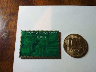
Recently I bought a small module called Ingenic Halley2. It's based on SoC Ingenic X1000. You can find the reviews in Internet about that board but they are all content same common information. No photos, no details.
I will try give more info about it.
There are some photos with my small debug stand.